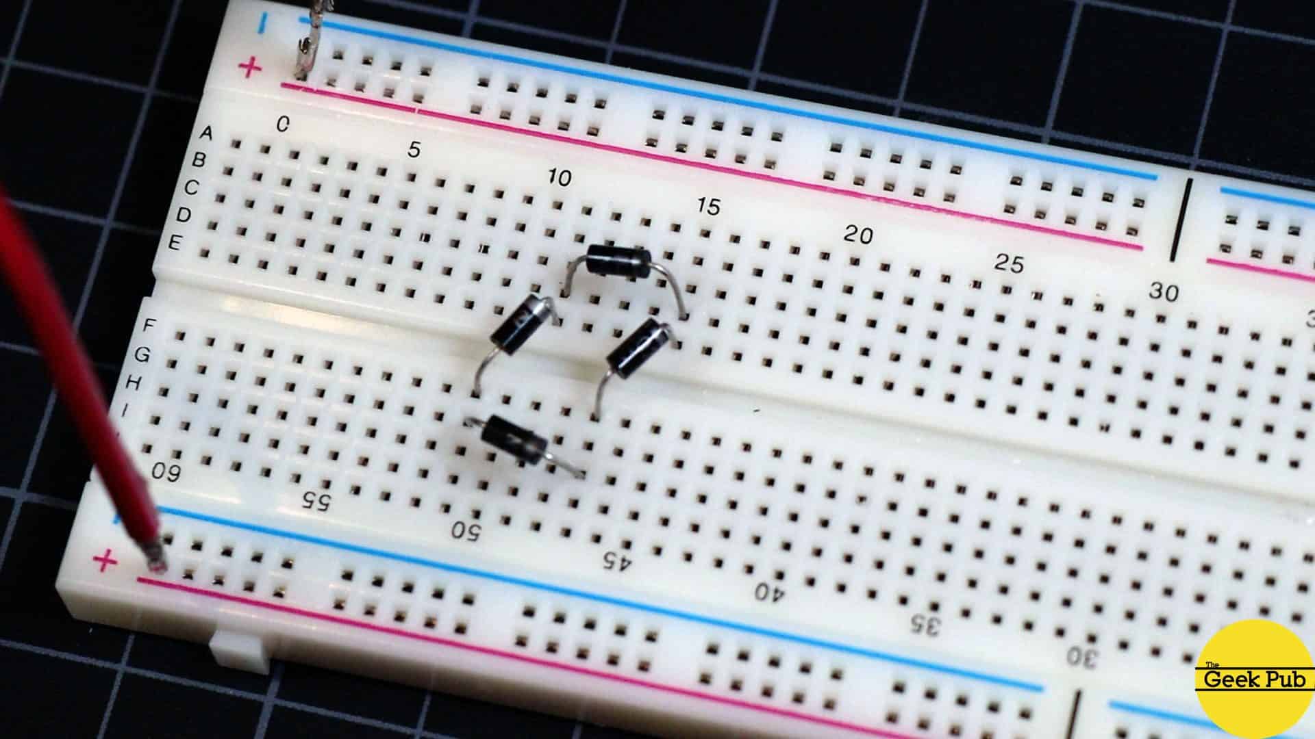
Bridge Rectifier Breadboard. Introduction this intractable page will guide you through all the steps necessary to build a full wave bridge rectifier. The electricity that comes out of a wall socket is ac current, while most modern electronic devices are powered by dc current. It is useful in converting ac current to dc. A very neat and compact layout of a bridge rectifier circuit on a prototyping breadboard. A bridge rectifier is an arrangement of four or more diodes in a bridge circuit configuration which provides the same output. Right now, i've got it. A full wave bridge rectifier is an electronic circuit that converts an ac current into a dc current. I want to throw it on a breadboard to test my circuit, and will eventally want to get it onto a pcb. In this detailed article, we will explore the intricacies of designing a full bridge rectifier pcb layout, covering various aspects such as component placement, trace routing,. My students should note that coursework. I have a bridge rectifier that has four flat blades on the bottom. Connect the positive power supply v+ (red wire) to the input.
from www.thegeekpub.com
A bridge rectifier is an arrangement of four or more diodes in a bridge circuit configuration which provides the same output. A full wave bridge rectifier is an electronic circuit that converts an ac current into a dc current. Right now, i've got it. In this detailed article, we will explore the intricacies of designing a full bridge rectifier pcb layout, covering various aspects such as component placement, trace routing,. Connect the positive power supply v+ (red wire) to the input. Introduction this intractable page will guide you through all the steps necessary to build a full wave bridge rectifier. It is useful in converting ac current to dc. I have a bridge rectifier that has four flat blades on the bottom. The electricity that comes out of a wall socket is ac current, while most modern electronic devices are powered by dc current. My students should note that coursework.
Building a USB Charger Circuit The Geek Pub
Bridge Rectifier Breadboard It is useful in converting ac current to dc. Connect the positive power supply v+ (red wire) to the input. A bridge rectifier is an arrangement of four or more diodes in a bridge circuit configuration which provides the same output. Introduction this intractable page will guide you through all the steps necessary to build a full wave bridge rectifier. I want to throw it on a breadboard to test my circuit, and will eventally want to get it onto a pcb. I have a bridge rectifier that has four flat blades on the bottom. Right now, i've got it. In this detailed article, we will explore the intricacies of designing a full bridge rectifier pcb layout, covering various aspects such as component placement, trace routing,. A very neat and compact layout of a bridge rectifier circuit on a prototyping breadboard. My students should note that coursework. A full wave bridge rectifier is an electronic circuit that converts an ac current into a dc current. The electricity that comes out of a wall socket is ac current, while most modern electronic devices are powered by dc current. It is useful in converting ac current to dc.